
Exploring Virtual Memory and Page Structures
September 2021
Recently, while taking a look at CCob’s BeaconEye tool to see how it works, I stumbled upon Frank Block and Andreas Dewald’s paper, Windows Memory Forensics: Detecting (Un)Intentionally Hidden Injected Code by Examining Page Table Entries. I was specifically looking for blogs and papers that would help me understand how various types of process injection could be detected. After giving it a read I decided to learn more about virtual memory and page table structures. I spent a few hours each night studying virtual memory and pages. I purchased a couple new books on the that had sections covering virtual memory and pages. Things finally clicked for me after after a while but, it didn’t come easy. I decided to write this blog help others and to help cement what I’ve learned. I hope the way that I present the information will be unique and helpful enough that others will find it useful.
This post will walk through the process of translating a virtual address to a physical address in a 4 level paging system used by Windows 10. The first portion of the post will focus on a very high level overview of what virtual memory paging is, then walk step by step through resolving a physical address from a virtual address, manually, with visuals, then finally demonstrate how this process can be performed in WinDbg.
Paged Virtual Memory & Context Switching Introduction
Each process running on a modern computer operates in its own context. Meaning that each process has its own virtual memory space for protection and to make better use of all of the memory available on a computer, including RAM and disk. A virtual memory address from one process is not valid in another in a another process. While it’s possible that two applications can share a memory page in physical memory, the virtual address each process uses will be unique to its context.
The operating system performs a series of changes to the CPU Eflags and Registers when moving from one process to another. This series of changes is called a context switch. The CR3 CPU Register in particular is important to process of context switching. The CR3 register is updated to contain the base address of the Page Map Level 4 (PML4) table for the current process. The PML4 table is the first in a series of tables that the Memory Management Unit (MMU) uses to resolve virtual memory addresses to physical memory addresses.
Page table structures and how virtual memory addresses are resolved will be covered in greater detail later. For now, it important to understand that each process has it’s own virtual memory space containing it’s own series of page tables and that the CR3 register points to the base of the PML4 table.
Page Table Types
The Intel® 64 and IA-32 Architectures Software Developer Manuals describe four paging modes, which are:
- 32-bit Paging
- Physical Address Extension (PAE) Paging
- 4-Level Paging
- 5-Level Paging
This post will focus on 4-Level Paging with a 64-bit processor. It was chosen because it is the the most common configuration I deal with and Windows 10 is currently using it. Once you understand 4-Level Paging, it should not be difficult to understand the other methods, as they all work similarly.
4-Level Paging Overview
As the name implies, there are four levels of page tables used in 4-Level Paging. Each page table has 512 entries. According to the Intel manual, 4-level paging uses 48-bit address. So if we have 4k (4096 byte) pages there can be a maximum of (2^48/2^12) = 2^36 page table entries referenced by each process. Each of the page table types, at all 4 levels, have a very similar structure as we’ll see. The four types of page tables are:
- Page Map Level 4 Table (PML4T)
- Page Directory Pointer Table (PDPT)
- Page Directory Table (PDT)
- Page Table (PT)
The following image is a spruced up version of the type of image you are likely to find if you search the Internet for information about memory virtualization or paging. This image depicts the 4-layer page mode with linear addressing. The following sections will detail the process of resolving a virtual address into a physical address. Hopefully, with a bit more explanation, the color codes and arrows will begin to make more sense.
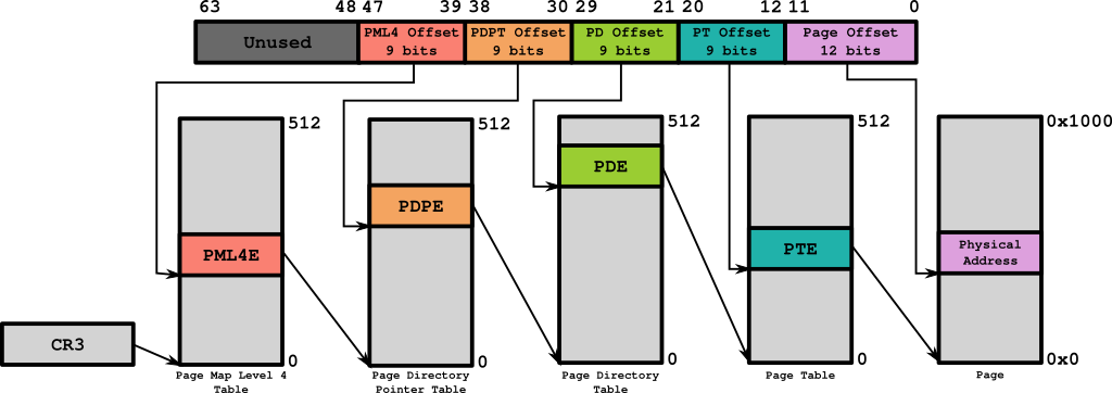
Figure 01: 4 Level Page Mode Overview
Resolving a Virtual Address (Manually)
This portion of the blog post will walk through the process of translating a virtual address using visual aids meant to better demonstrate the process of resolving a virtual address to a physical address. I read several books and blogs while trying to learn this, visualizing the process this way is what finally made it click for me. Hopefully, this will help others as well. To get started a virtual address to translate to a physical address is required.
The Virtual Address
The virtual address, 0x00007FF6`0BF40190, is an example from a virtual machine that I used to gather material for my notes and this blog. It happened to point to the entry point of a notepad.exe process running on my debugee machine. The second half of this blog will describe how to use WinDbg to locate the entry point of a process. Below is a visualization of the address in binary and split to represent each offset it contains.
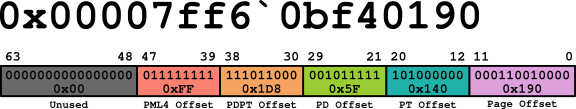
Figure 02: Virtual Address Visual
Each of the page table structure offsets are 9 bits in length. This means that the offset value can be a minimum of 000000000 in binary (0) and a maximum of 111111111 in binary (511). This means that each page table structure can contain a maximum of 512 entries. Each entry is 0x08 (8) bytes in length.
The page offset is larger, it can contain a minimum value of 0 and a maximum of 4095. 4096 bytes is the number of bytes in 4 kilobytes (kb). This means that the maximum page size, in this example, is 4 kb. It also means that, unlike a page table offset, this offset will represent the number of bytes from the base address of the page, not page table entry number.
Locating the Base Address of the Page Map Level 4 Table (PML4T)
As previously mentioned, the base address of the Page Map Level 4 Table (PML4T) address is stored in the CR3 register and each processes has it’s own virtual address space. Therefor, within each process’ context a unique value stored in the CR3 register. The value stored in the CR3 register is also the same as the value stored in the DirectoryTableBase element of the KPROCESS structure, which is pointed to by the Pcb element of the EPROCESS structure.
If attempting to write a kernel driver to find the base address of the PML4 table, you could use the PsLookupProcessByProcessId Win32 API to locate a process’ EPROCESS structure, then retrieve the base address of the PML4 table from the Pcb (KPROCESS) element. The value stored in the CR3 register for this example was: 0x00000000`7087B000.
Locating the Page Map Level 4 Entry (PML4E) Address
The PML4T offset is 0xFF (255). (See Figure 02) To find the address of the 255th PML4T entry:
- The number of bytes in each Page Map Level 4 Entry (PML4E) entry (8 bytes) must be multiplied by the offset value (255).
- The result is then added to the base address of the PML4T.
The calculation is demonstrated in Figure 03. Completing the calculation reveals that the PML4E is located at the address: 0x000000`7087B7F8.

Figure 03: Calculating the Address PML4 Entry
Locating the Base Address of the Page Directory Pointer Table (PDPT)
Continuing the example, the value stored in the PML4E from the previous step was: 0x0A000000`70c87867. To derive the base address of the Page Directory Pointer Table (PDPT) from this value, it is necessary to understand the structure of a Page Table Entry that maps to a 4 kb page. Table 4-19 of the Intel® 64 and IA-32 Architectures Software Developer Manuals details what each bit position represents. Figure 04 represents the structure of a PML4E. Table 01 describes what each segment of bits is used for. For the purpose of this blog post, bits 12 through 36 are what we will need to calculate the PDPT’s base address.

Figure 04: PML4E Structure
| Bit Position(s) | Key | Description |
|---|---|---|
| 0 | Present | Whether or not the page table entry is present. Must be 1 to be a valid entry. |
| 1 | Read/Write | Whether or not the page referenced by the page is writable. Must be 1 to be writable. |
| 2 | User/Supervisor | Whether or not the page can be access in user mode. Must be 1 to be user accessible. |
| 3 | Page-Level Write-Through | Determines the type of memory referenced by the page table entry. |
| 4 | Page-Level Cache Disable | Determines the type of memory referenced by the page table entry. |
| 5 | Accessed | Whether or not the page has been accessed. If the value is 1, the page has been accessed. |
| 6 | Ignored | Ignored |
| 7 | Reserved | Reserved |
| 8 - 11 | Ignored | Ignored |
| 12 - 36 | PDPT Address | The physical address of the PDPT’s base. |
| 37 - 51 | Reserved | Reserved |
| 52 - 62 | Ignored | Ignored |
| 63 | Execute Disabled | Whether or not code execution is disabled on the referenced page. If the value is 1, execution is disabled. |
Table 01: PML4 Value Descriptions
To locate the PDPT’s base address using the value stored in the PML4T entry, bits 12 through 36 must first be extracted/isolated. Figure 05 is a visual representation of the steps performed to extract the physical address of the PDPT.
To isolate bits 12 through 36, a bitwise AND operation is performed using the PML4E value and 0x00000000`FFFFF000. 0x00000000`FFFFFF000 is a bitmask with only bits 12 though 36 set to 1 (true). When the bitwise AND is performed only bits 12 through 36 of the PML4E will remain . This value is the base address of the PDPT. The PDPT Base Address in the example was: 0x00000000`70C87000.

Figure 05: Deriving the PDPT Base Address Using a Bitmask
Locating the Page Directory Pointer Entry (PDPE)
The process of finding the PDPE in the PDPT is, essentially, the same process as finding the PML4E in the PML4T. Like the PML4T, the PDPT also has 512 entries that are each 0x08 bytes in length. Figure 06 shows the calculation and the resulting value: 0x00000000`70C87EC0.

Figure 06: Calculating the PDPTE Address
Locating the Base Address of the Page Directory (PD)
The process of locating the base address of the PD is identical to the process of locating the base address of the PDPT. The value stored in the PDPE from the previous step was: 0x0A000000`70884867. As demonstrated in Figure 07, when a bitwise AND is performed using the mask 0x00000000`FFFFF000, the base address of the PD is revealed: 0x00000000`70994000.

Figure 07: Deriving the PD Base Address Using a Bitmask
Locating the Page Directory Entry (PDE)
The PDE can be located by using the base address of the PD from the previous step and the offset (0x5F) from the virtual address. The calculation is performed the same way that the PML4E and PDPTE have been done. Figure 08 demonstrates the calculation. 0x00000000`709942F8 was the address of the PDE in this example.

Figure 08: Calculating the PDE Address
Locating the Base Address of the Page Table (PT)
The calculation used to locate the base address of the PML4T, PDPT, and PD base addresses is used to locate the base address of the PT, one final time. The value stored in the PDE in our example was: 0x0A000000`70C95867. The bitwise AND performed using this value and the mask 0x00000000`FFFFF000 can be seen in Figure 09. The base address of the PT was: 0x00000000`70C95000.

Figure 09: Deriving the PT Base Address Using a Bitmask
Locating the Page Table Entry (PTE)
At this point in the process, things should seem very familiar. For completeness, this blog will complete all steps required to translate the physical address. If, however, at this point you are comfortable with the process and wish to know how to perform these same steps in WinDbg, feel free to skip to the end.
Using the PT’s base address, the calculation to find the PTE at offset (0x140) can be seen in Figure 10. The PTE in the example was located at the address: 0x00000000`70C95A00.

Figure 10: Calculating the PTE Address
Locating the Base Address of the Page
This is the next to last calculation required to resolve the virtual address. This step will find the base address of the Page. The next step will be to find the physical address. The value stored in the PTE at the address 0x00000000`70C95A00 was 0x01000000`6BAB7025. The bitwise AND operation using the mask 0x00000000`FFFFF000 results in the address 0x00000000`6BAB7000. Figure 11 demonstrates the calculation.

Figure 11: Deriving the Page Base Address Using a Bitmask
Locating the Physical Address
This is the final step. After adding the Page offset to the Page’s base address, the physical address will be revealed. This step is where the process deviates from the pattern that has been established in the page table entry calculations. As previously described, the Page Offset value in the virtual address is large enough to cover values between 0 and 4095. This offset is the byte offset from the base of the Page. There is no need to multiply it by the size of of a page table entry. This being the case, you simply add the offset (0x190) to the Page’s base address to get 0x00000000`6BAB7190. This address is the Physical Address that the virtual address 0x00007FF6`0BF40190 points to.

Figure 12: Calculating the Physical Address
Resolving a Virtual Address with WinDbg (Also Manually but with help.)
This section will not walk completely through the process but it will, instead, offer some assistance in the way of WinDbg commands and calculations that can be used to translate a virtual address to a physical one. To do this, you will need to have a Kernel debugging session setup. For learning purposes, I have found that using two virtual machines with a host-only network works well.
Locating a Virtual Address to Translate
In the manual example, the notepad.exe process running on the target machine (debugee) had been used to demonstrate the process. The same virtual address and process will be used in the WinDbg examples. This will hopefully allow the reader to compare the manual process to what is being performed in WinDbg. Before using WinDbg to break execution (CTRL+PAUSE/BREAK) in the Kernel debugger, start a notepad.exe process. You can use anything you like, just be replace notepad.exe with whatever process you choose.
Switching the Process Context
-
Once the target process is started on the debugee, press CTRL+PAUSE/BREAK to break execution.
-
Use the following command to locate information about the process you started:
!process 0 0 notepad.exeCode 01: Using the !process command to obtain information about the notepad.exe process
NOTE: Replace notepad.exe with the process you chose to work with.
- Use the virtual address that is listed next to PROCESS in the output of the previous command to change WinDbg to the context of the target process. This is done with the .process command:
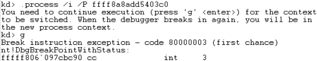
Figure 13: Changing Process Context
- After you run the .process command, you will need to start the process with the g command. The process should immediately break. This is necessary to allow the process context change to complete. See Figure 13 for an example of how this looks.
- Once the debugger hits the int 3 break. The next step is to reload the symbols for the current process. To do this, run the following command:
.reload /fCode 02: Reloading the symbols after switching the process context.
Locating a Virtual Address
In this example, the processes entry point will be our target. The following steps will guide you though the process of finding the virtual address of a process’ entry point. The remainder of the steps will walk through the steps and calculations necessary to translate the address to a physical address.
- Dump the headers of the process using the !du command. In the OPTIONAL HEADER VALUES section look for address of entry point. This value (20190) is the offset from the base address of the the notepad.exe process stored in memory.
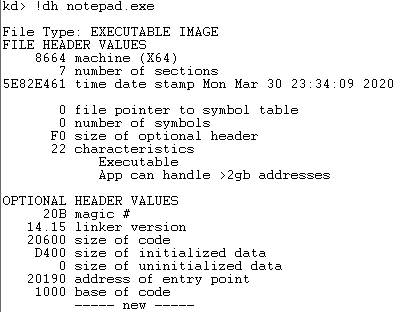
Figure 14: Dumping the process headers
- Using the u command, it is possible to confirm that this offeset is correct. The following command can unassemble the code at the calculated address. See Figure 15 for an example that reveals that the WinMainCRTStartup has been located.
u notepad.exe + 0x<address_of_entry_point>Code 03: Disassembling notepad.exe’s entry point by the calculated address.
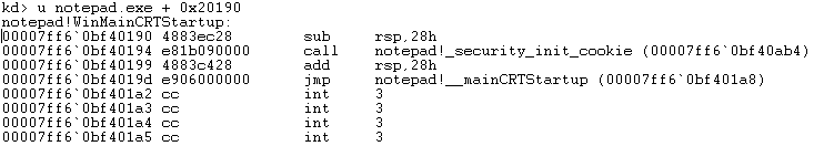
Figure 15: Unassembling the entry point
- Now that the hard way has been demonstrated, There is an easier way. Use the u command to disassemble WinMainCRTStartup directly by issuing the following command:
u notepad.exe!WinMainCRTStartupCode 04: Disassembling notepad.exe’s entry point using WinMainCRTStartup.
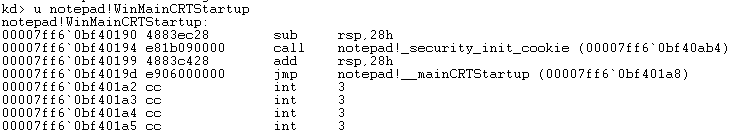
Figure 16: Unassembling the entry point using WinMainCRTStartup
In both of the above examples, the virtual address that represents the entry point of the notepad.exe has been located: 0x00007FF6`0BF40190. The following steps will provide some examples of the commands in WinDbg that can be used to translate the address to a physical one.
Breaking Down the Virtual Address to Find the Offsets
To get the offsets for the PML4, PDPT, PD, PT, and Page you can use the .formats and evaluate (?) commands in WinDbg. This can be accomplished by using a series of bitmasks and rotation operations. The following steps will walk through the process. Since this article already demonstrated the process by hand above, this section will demonstrate the calculations, once, then provide a table of the formulas that can be used to calculate the remainder of the offsets.
- To calculate the PML4E offset value, enter the following command. This command will perform a bitwise AND opperation using a bitmask that will leave only the bytes specific to the PML4E offset value. It will then rotate the bits right 0x27 (39) bits. When the following formula is evaluated the PML4E offset 0x00000000`000000ff (255) is found.
? (0x00007ff6`0bf40190 & 0x0000FF80`00000000) >> 0x27Code 05: Locating the PML4 Offset using WinDbg
The following table demonstrates the formulas that you can use to calculate each offset. If you convert these bitmasks to binary and compare them to Figure 02 you will notice that the only bits that are set to 1 (true) are the ones that correspond with the offset being recovered. The bit rotation (») rotates the bits to the right by the number of bits between position 0 and the start of the offset value being calculated.
| Offset Type | Expression to Evaluate* |
|---|---|
| PML4 | ? (<Virtual_Address> & 0x0000FF80`00000000) » 0x27 |
| PDPT | ? (<Virtual_Address> & 0x0000007F`C0000000) » 0x1E |
| PD | ? (<Virtual_Address> & 0x00000000`3FE00000) » 0x15 |
| PT | ? (<\Virtual_Address> & 0x00000000`001FF000) » 0x0C |
| Page | ? (<Virtual_Address> & 0x00000000`00000FFF) |
*Replace <Virtual_Address> with the virtual address you are calculating offsets for.
Tabel 02: Page Offset Offset Formulas
Locating the Page Map Level 4 Entry (PML4E) using WinDbg
To find the PML4E you will first need to obtain the value stored in the CR3 register. With that value you can quickly perform an evaluation to obtain the address of the base of the PDPT.
- To obtain base address of the PML4 table, enter the following command:
r cr3Code 06: Locating the PML4 Base Address.
- To obtain the address of the PML4E, enter the following formula. In the example scenario CR3 is 0x00000000`7087B000 and the offset is 0xFF. The result of evaluating the formula with those values is: 0x00000000`7087B7F8.
? @cr3 + <PML4_Offset> * 0x08Code 07: Calculating the PML4E’s address using WinDbg.
Locating the Page Directory Page Entry (PDPE) Value Using WinDbg
The value, in this example, stored at the PML4E is 0x0A000000`70C87867. Evaluating the following formula will result in the address of the PDPE.
? (<PAGE_Entry_Value> & 0x00000000`FFFFF000) + <Page_Entry_Offset> * 0x08Code 08: The formula to calculate a Page Table Entry.
Plugging in the values, including the offset of 0x1D8 we find the that the PDPE address is: 0x00000000`70C87EC0.
? (0x0A000000`70C87867 & 0x00000000`FFFFF000) + 0x00000000`000001d8 * 0x08Code 09: Calculating the PDPE’s address using WinDbg.
Locating the Page Directory Entry (PDE) Value Using WinDbg
The value stored at at the PDPE is 0x0A000000`70994867 in the example. The formula is the same for all Page Tables. This means evaluating the following expression will result in the address of the PDE. The resulting vlaue is: 0x00000000`709942F8.
? (0x0A000000`70994867 & 0x00000000`FFFFF000) + 0x00000000`0000005f * 0x08Code 10: Calculating the PDE’s address using WinDbg.
Locating the Page Table Entry (PTE) Value Using WinDbg
This will be the last time using the page table formula. The value stored at the PDE in the current example is: 0x0A000000`70C95867. Evaluating the following expression will result in the value 0x00000000`70C95A00.
? (0x0A000000`70C95867 & 0x00000000`FFFFF000) + 0x00000000`00000140 * 0x08Code 11: Calculating the PTE’s address using WinDbg.
Resolving the Physical Address Using WinDbg
The final calculation is a bit different since the Page Offset value is an actual byte offset. There is no need for multiplication to find a specific entry. In the running example, the value 0x01000000`6BAB7025 was stored in the PTE. If we plug that into the following formula, we get the address 0x00000000`6BAB7190, which is the physical address in this example.
? (0x01000000`6BAB7025 & 0x00000000`FFFFF000) + 0x190Code 12: Calculating the physical memory address.
Conclusion
In this rather lengthy blog post, I have demonstrated how to resolve a virutal address manually and with WinDbg. This is a small part of what I set out to learn after reading Frank Block and Andreas Dewald’s white paper describing how to detect injected code by enumerating virtual memory pages. It seemed like a bit of magic and I wanted to learn more. While attempting to learn more, I came across several explanations of how page tables worked, and how perform the calculations but they were not easy for me to understand. Once I did, it felt the need to document what I had learned so that others might find it useful.
I intend to keep going and build upon what I have learned. My next step is to attempt to create a Kernel driver that will be capable of walking all processes and dumping some information about each process’ page tables and pages. I would like to create an application that can duplicate the process described in the whitepaper. From there, who knows? I’ll just keep building on what I have learned.